

Kenwood TR751A – pot replacements
The Kenwood TR751A 25w multimode radio for 144 – 148 MHz is well regarded, with a sensitive receiver and good transmit quality. However the pots installed as dual concentric types for the AF Gain, RF Gain, Squelch and RIT functions have a reputation for failing. The manufacturer has discontinued supplying spare parts for these radios as they are now about 30 years old.
A source of replacements was identified in very similar pots stocked as spares for a Ranger CB radio at R&R Communications in the USA. This source was documented by members of the Yahoo Group for TR751 and TR851. (The group recently moved to groups.io).
I ordered and received the replacement pots but had not installed them, the job waited on the back burner while I was preoccupied with other matters. With my interest in portable operations on 2m ssb/cw I realised that this radio could provide the additional power I sometimes wanted (additional over the FT817’s 5 watts) and could be a useful part of my portable operations. I am aware that the increase amounts to only 7dB but sometimes that makes the difference when using small antennas you’ve carried up to a summit and reassembled there.
After removing top and bottom covers, knobs and the front panel cover, I removed the two pots, unplugging the cables from their headers on the PCBs mounted on both pots. Desoldering the old pots from the boards was a long winded process and I found that my solder wick was not working as it should. I suspect the solder originally used has a different ratio of tin:lead and therefore needs slightly higher temperature than the 60:40 I usually use. Eventually the pots were off the boards and the new problem was to fit the replacement pots. The spacing between the three pins of the front pot section and the pins of the rear pot was quite different between old and new pots. I decided to put in small extensions for the pins of the rear pot. This was done using wire that was cut from resistors and capacitors after being soldered onto a PCB for a filter kit. Also the switch connections were different, requiring a jumper to be inserted between two pins on the PCB.
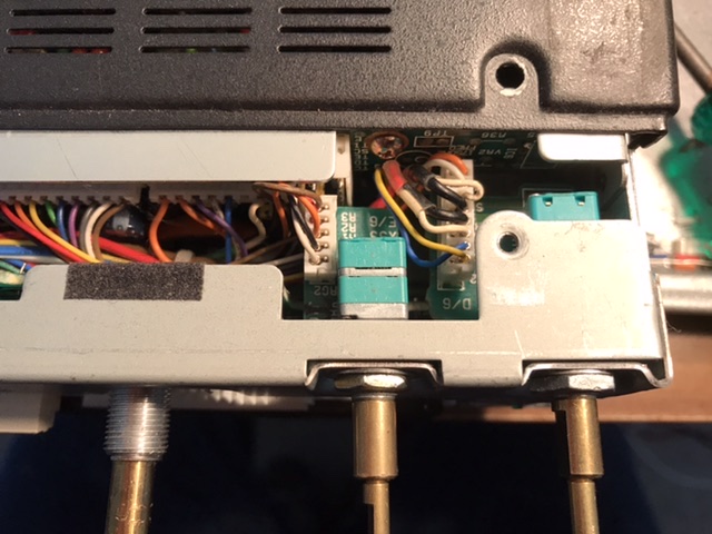
Following reassembly, the new pots appeared to protrude from the front panel much further than the originals did. I found this could be largely resolved by installing an extra nut on the control to effectively position the pot further behind the front panel. The pic following shows the result of this adjustment. A minimal amount of threaded shaft protrudes in front of the mounting panel. The limiting factor was the PCB visible here that is pushed against the assembly behind it, in fact I had to wind this pot a little bit forward because I couldn’t return the front panel assembly fully to its correct position without doing that.
Once back together the radio was tested ok and later I used it for a test on SSB from Black Mt, Canberra. I had a quite successful activation on 2m ssb, making contacts into Sydney (about 270 km) and to Nimmitabel (about 100km) using the TR751 and a loop antenna that had been lent to me by Andrew vk1ad. it was mounted on a short fibreglass pole.
During the testing of the radio I was pleased to see that its current drain on receive was 400 mA, which is slightly less than the FT817. On transmit full power it drew almost 6 amps. No problem for the LIFEPO4 battery normally used, which has a 20C rating, meaning it can provide 20 times its AH rating. 4.2 x 20 is 85 amps. the relatively low current drain on receive means this radio is a good option for using on battery powered activations. By comparison the IC706 or FT857 style radio would draw twice that current on receive. On transmit, the bias level of the final amplifier would double that current even before producing any RF. Turning the power level down on the higher power radio to its minimum of say 5 watts does not change that bias current, so running those higher powered radios at low power is very inefficient. It doesn’t matter if you only want 30 minutes of operation, but the same power consumed by the 706 in 30 minutes of reception would run the TR751 for at least double and possibly 4 times the 30 minutes.

Icom IC703 portable HF multimode transceiver
This rig was my primary HF rig for SOTA and parks activations. But it developed a problem in the VFO circuitry, behaving as though the dial was slipping. Turning the dial would normally result in the frequency changing continuously. However the fault was causing the frequency to freeze occasionally. I didn’t mind turning the dial a bit more but I thought that if some of the components in the encoder were faulty, maybe more would be faulty before too long and I should replace it.
I ordered the part from Icom Australia and it turned up after a predicted delay as it had been out of stock. I was told the part is used in multiple other radios including the recently released IC9700. It was reassuring to know the part was still in production.
The vfo encoder is located in the control panel for the radio. It just sends up and down signals back to the main unit. It is based on a set of LEDs and detectors, I assume light dependent resistors, arranged In a circular pattern at regular spacings around a central shaft. A circular disc with a set of holes or windows cut into it at specific positions corresponding to the LEDs allows light to pass through from the LED to the LDR. The vfo tuning direction is deduced from the timing of when light is first detected by each sensor, compared with a twin located slightly more or less than 180 degrees further around the circle. If the sequence of light detection is the sensor at 0 degrees followed by the sensor at 181 degrees, the dial must be turning clockwise so the frequency is required to move up. and vice versa when the dial is turned anti clockwise. Well, that’s how i understand it. The entire assembly is sealed into a small package looking like a potentiometer and has a cable terminated in a small plug.
The control panel for the IC 703 is very similar to that of the 706. I think it’s likely that the 706 front panel looks identical inside and this fix would apply to that radio series too.

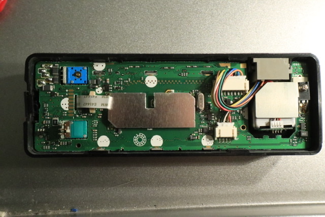
Top right is the grey RJ series microphone connector, below that and behind the shield plate is the encoder. I unscrewed the nut on the encoder first. The PCB has to be lifted out of the case, a procedure I performed with a lot of care for fear of damaging the board or traces on it. Once the PCB is removed the encoder can be removed and the new one installed in its place. I removed the mike connector to get easier access to the encoder.

After that I replaced the knob on the encoder shaft but it was loose and i couldn’t see how it was attached. Many knobs on Icom radios have a grub screw inside the knob, covered up by the rubberised section around the knob. Removing the rubber revealed nothing of the sort. Looking for help on the web I found reference to a small spring steel clip inside the knob. There was none inside mine. Then I found it on the workbench where it had fallen out when I originally removed the knob. A bit of careful work with tweezers put it back into the knob and the knob then went back onto the shaft and stayed there.

Reassembled, the acid test was to turn it back on. Initially it appeared to be dead. I recalled a reset procedure and tried that without effect. Reading the manual page on the reset I found the correct procedure was to hold the up and down buttons then press power. Following that procedure the rig came alive, to my great relief, and I was able to tune in some broadcast stations using a 50cm piece of wire.
I then had to take the rig out for a field test to confirm it is back to normal. It was, and it was good to have the radio working normally again.

You must be logged in to post a comment.